With the adoption of the "B" design (A-17553) wiper, the wiper was not only improved but the design considerably simplified. In addition the change also made it comparatively easy to make repairs on this later design wiper.
We are accordingly shipping a supply of "B" design wiper parts to all Branches so that dealers can obtain these parts and furnish owners complete service on the "B" type wiper.
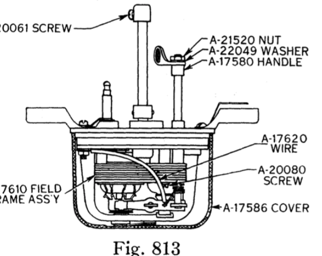
((813))
REPAIRING "B" TYPE WIPERS
When a wiper fails to operate first make certain that you have a good clean and tight connection at the ground on the windshield frame. Also that you have a good connection at the A-14471 connector. Next take off the cover and thoroughly clean the commutator with a piece of 00 sandpaper. If this fails to remedy the trouble, it will be necessary to remove the wiper and check it as follows:
GENERAL
Remove the cover from the windshield wiper, and make a, visual inspection to determine, if possible, whether there are any loose or broken connections. The circuit through the wiper starts at terminal (A-17621) shown in Fig. 815, and passes through the brass connector and screw in the corner of the base, then through the black covered wire (A-17620) shown in Fig. 813, to the upper brush holder. From there it passes through the armature to the other brush holder, and through the field winding to the ground connection which is under screw (A-20080) shown in Fig. 813. This screw is located beside the switch shaft. The circuit can be checked by striking the battery wires at various points along this circuit. If a spark is produced, the current is flowing up to the point where the spark occurs. If the circuit is found to be continuous, raise the brush (see Fig. 814) from the commutator. This is the brush to which the end of the field is connected. Connect one battery wire to the base. When the other wire is attached to the line terminal no spark should occur. If the wire produces a spark there is a short in the line terminal, or ground in the armature. The armature should revolve freely when turned with the fingers. If the armature is tight, the trouble may be armature bearings or tight gears.
GEAR CASE
To open the gear case, first remove the wiper lever shaft (A-17567) Fig. 815. This is accomplished by removing the screw which holds the small bearing cap, and pulling the shaft straight out of the base. Next remove screw (A-20080) (see Fig. 813) that connects the line terminal with the wire inside of the base, taking care not to lose the insulating washers. Remove the two screws (A-20076) Fig. 816, in the back of the wiper, which will also remove ground strap (A-17617) shown in Fig. 816. This opens the gear compartment and permits free access to the gears. Before pulling the gear case apart, it is advisable to reach through the wiper shaft hole and with the point of a knife or other sharply pointed instrument, raise the rack up in front of the hole. The reason for doing this is that the oscillating rack is hooked behind a backing up pin which is attached in the base. If not raised the rack may stay with the gears and should it do so, it may become bent when removing the base.
The gear case contains two gears, known as the idler gear (A-17588-B) and the eccentric gear (A-17614-B), see Fig. 817. The ratio of these gears is 72 to 1. The idler gear, which is made of bakelite, meshes with the pinion on the end of the armature shaft and is mounted on a small pinion having a hole through the center. The pinion is supported on idler gear pin (A-17615) Fig. 817, which enters a hole in each side of the gear case. This gear should not turn on its pinion. If the gear turns on its pinion, it will be necessary to replace the idler gear assembly (A-17588-B). The idler gear pinion meshes with the eccentric gear, upon which is mounted the eccentric which drives the oscillating rack (A-17612) Fig. 817. This rack moves back and forth and meshes with the small gear on the wiper shaft assembly, causing this shaft to produce an oscillating motion. There is sometimes a ticking sound produced by the wiper. This sound is somewhat similar to the timing apparatus in a taximeter. The noise is caused by a chip or dirt in the teeth of the intermediate gear, and can be removed by carefully examining the gear teeth and picking the dirt out of the bottom of them. When the gear case has been opened, the gears should always be re-packed with grease of similar quality to that originally placed in the wiper. Do not use too much grease as it will work out of the wiper shaft and into the inside of the motor. Too little grease is liable to cause noise and tight bearings. In replacing the gears in the case, the gears are assembled on the motor frame. Mesh the idler gear with the armature shaft and insert the idler gear pin into the hole in the motor frame. This should be free. Place the eccentric gear in mesh with the intermediate gear so that the eccentric is farthest away from the wiper shaft hole. The rack is now placed on the eccentric as shown in Fig. 817, and over the wiper shaft hole. Place the gasket (A-17611) Fig. 814, over the motor frame. The base can now be slipped down over the wiper shaft without damage or derangement of the gears and rack. Replace the screws in the gear case in the order in which they were removed, being careful to assemble the insulating washers in the small grooves provided for them in the base and motor frame. With the end of a small screw driver or similar tool, push the rack down until it is seated behind the backing-up pin in the base. The wiper shaft can now be replaced by placing the wiper lever on the side of the wiper nearest the line terminal, as shown (dotted) in Fig. 816, and meshing the wiper shaft gear with the last tooth in the rack that will bring the lever closest to the base foot. The bearing cap screw can then be screwed in tight.
The factors controlling the timing of the wiper shaft are: having the eccentric located at the limit of its stroke away from the wiper shaft hole and having the wiper shaft lever at the limit of its stroke on the same side of the windshield wiper. The wiper shaft is driven through the medium of a safety clutch. This safety clutch is a part of the wiper shaft assembly. The purpose of this clutch is to protect the gear mechanism if it becomes necessary to move the wiper blade for washing the windshield or for any other purpose. This clutch should disengage with a sharp quick motion applied to the wiper blade arm, or the hand wiper lever. If the clutch does not disengage under these conditions, the clutch spring may be too stiff. This clutch is shown in section “C,” Fig. 815. The clutch can be weakened by removing the pin in the end of the wiper shaft, removing the spring and grinding it slightly shorter. Sometimes the clutch is tight, due to having been operated dry and the clutch pin has become scored. It may be necessary to smooth the pin or the notch in the gear with a fine stone. If the clutch is too weak, it can be strengthened by slightly pulling out the spring, taking care that too much tension is not put on the clutch.
ARMATURE AND FIELDS
There are three common troubles occurring in all armatures. They are shorts, grounds and opens. It · will be necessary to replace the armature (A-17606-B) Fig. 819, if any of these troubles exist, as it is rather difficult without proper equipment to test and locate these troubles. The rewinding of this armature is also difficult, as it is done on a special winding machine with special wire. There is rarely any trouble with the winding of the field (A-17610) Fig. 813. The only difficulty experienced with the field frame assembly is the possibility of it not being properly centered around the armature. If the field frame is not properly centered there is liable to be noise produced by the motor. The air gap around the .armature should be even at all points. If it is not, loosen the screws holding the field frame and tap it slightly in the. proper direction to make the air gap uniform.
SWITCH AND BRUSHES
The stopping of the windshield wiper 1s accomplished by a switch shaft on which is mounted a small fibre disc. This disc when turned lifts one of the brushes from the commutator. The brush lift from the commutator should not be more than 1/16 of an inch, nor less than 1/32 of an inch. If the brush lifts more than 1/16 of an inch, it may strike the inside of the cover and the black wire connected to this brush may be burned out. If this wire is burned out in the wiper, it generally indicates that the brush holder has been in contact with the inside of the cover. However, the wire can be burned by a heavy ground in the armature. One common source of trouble is the fit of the brushes on the commutator, also the cleanliness of the commutator. If the commutator is dirty, it should be cleaned with No. 00 sandpaper only. Do not use a file or emery doth. If the brushes are noisy and rattle, they can be quieted by having the arc on the inner surface of the brush fit evenly with the contour of the commutator. A drop of a good grade of light oil placed on the commutator will also assist in quiet brush operation.
When the wiper is mounted on the car, the spring wiper arm should be adjusted so that the blade bears against the glass with a pressure of between three and four ounces at the point where the blade attaches to the wiper arm. If the pressure is maintained no higher than four ounces, there will be little fatiguing of the rubber in contact with the glass.
WINDSHIELD WIPER PARTS FOR SERVICE
A complete list of the windshield wiper parts that will be supplied for service is printed on the next page.
Parts marked "old" apply to wipers with the stamped bridge. Parts marked "new" apply to wipers having the die cast bridge. Parts not marked "old" or "new" apply to wipers having either the stamped or die cast bridge.