((523))
Brake rods have been redesigned making them into a solid nonadjustable type. The rods now have a single eye forged on each end in- stead of having an adjustable clevis at one end. This arrangement assures a fixed length rod and simplifies brake adjustments. It also eliminates the use of stops in the back flange of the center cross member.
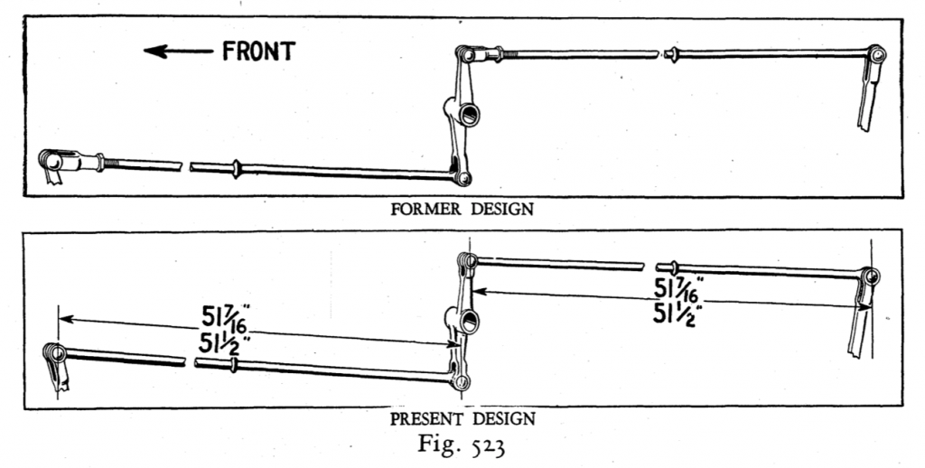
The change to nonadjustable brake rods necessitated changing the front brake lever and the upper end of the outer lever on the cross shaft assembly, from a single eye end to a clevis. Fig. 523 shows the old and new design rods and levers.
Servicing Brake Rods
Should it become necessary to install a new brake rod on a car equipped with adjustable rods, an adjustable rod can be easily made from a solid rod by sawing off the end of the rod 1/4” back from the center of the eye and running a 5/8-24 thread back 2” from the end and installing the adjustable clevis and lock nut. The length of the rod should be adjusted to not less than 51 7/16 or more than 51 1/2.
A one-piece brake cross shaft assembly h a s also been adopted (A-2485-6-C) superseding the former design in which the shaft and end levers were individual items.
Should it become necessary to replace a brake cross shaft assembly A-2485 or 6-AR, install the latest type cross shaft assembly A-2485 or 6-C together with the solid type rear rod.
Adjusting Brakes
Instructions for adjusting brakes on cars equipped with adjustable rods were given on Pages 202. and 103 of the January Bulletin. The instructions on Page 202 with the exception of the last four paragraphs also apply to adjusting brakes on cars equipped with solid rods